Task: Get a LED to blink.
Required equipment: Just the microcontroller board with the USB cable.
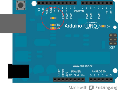
On the board a LED is already build on the pin 13 (for test purpose). This LED often already blinks, after connecting a new board to the computer, because during manufacturing the blink program is uploaded for test purposes. We are going to program this blinking by ourself.
Circuit:
The meant LED is circled in red on the image above.
You only have to connect the board properly with the computer.
1.1 First part of the program: Name variables
– First we don’t do anything here.
1.2 Second part of the program: Setup
We only have one output – Pin 13 should put out voltage (The LED should light up.).
We start writing in the white area of the arduino software:
void setup() //The setup begins here
{ //opening curly bracket – A program part begins here
} //closing curly bracket – A program part is ending here
Now we are going to write the setup information between the curly brackets.
In this case: “pin 13 is supposed to be an output”:
void setup() //The setup begins here
{ //A program part begins here
pinMode(13, OUTPUT); //Pin 13 is supposed to be an ouput.
} //A program part is ending here.
1.3 Third part of the program: Loop (main part):
void setup() //The setup begins here
{ //A program part begins here
pinMode(13, OUTPUT); //Pin 13 is supposed to be an ouput.
} //A program part is ending here.
void loop() //The main part of the program begins here
{ //A program part begins here
} //A program part is ending here.
Now we bring in the loop part (main part).
THIS IS THE COMPLETE SKETCH:
void setup() //The setup begins here
{ //A program part begins here
pinMode(13, OUTPUT); //Pin 13 is supposed to be an ouput.
} //A program part is ending here.
void loop() //The main part of the program begins here
{ //program part begins here
digitalWrite(13, HIGH); //Turn on the voltage on pin 13 (LED on)
delay(1000); //Wait for 1000 milliseconds (one second)
digitalWrite(13, LOW); //Turn off the voltage on pin 13 (LED off)
delay(1000); //Wait for 1000 milliseconds (one second)
} //Program ends her
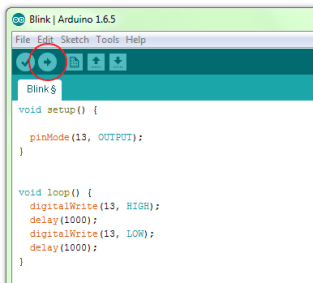
Done! The sketch should look just like the one in the image on the right. Now we have to upload it to the board. By clicking on the button with the arrow on the upper left of the software, you will upload the sketch to the board.
1.4 Now you have the option to modify the program. Example: You want the LED to
blink really fast. Therefore we will shorten the waiting time ( From 1000ms to 200ms)
void setup() //The setup begins here
{ //A program part begins here
pinMode(13, OUTPUT); //Pin 13 is supposed to be an ouput.
} //A program part is ending here.
void loop() //The main part of the program begins here
{ //program part begins here
digitalWrite(13, HIGH); //Turn on the voltage on pin 13 (LED on)
delay(200); //Wait for 200 milliseconds
digitalWrite(13, LOW); //Turn off the voltage on pin 13 (LED off)
delay(200); //Wait for 200 milliseconds
} //program part ends.
The new modified sketch has to be uploaded to the board again. Now if everything has worked properly the LED should blink faster.