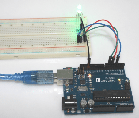
Task: We want a RGB LED to light up in different colours.
Required equipment: Microcontroller / one RGB LED / three resistors each with 200 Ohm / Breadboard / cables
What is an RGB LED? The RGB LED is an LED that is able to shine in different colours.
RGB stands for the three colours “red”, “green” and “blue”. Inside the RGB LED are three separate LEDs available, which can be turned on and off individually and shine in three different colours. That is reason behind the four contacts of the RGB LED. The longest one can be (depending on the version) the anode(+) or the cathode(-). The other contacts belong to the different colours.
Version a; “Common cathode” – The longest contact of the RGB LED is “-”. In this case the other three contacts are supposed to get positive gate voltage (5V) “+”.
Version b: “Common anode” – The longest contact of the RGB LED is “+”. This means that the other contacts are supposed to get negative gate Voltage (GND) “-”.
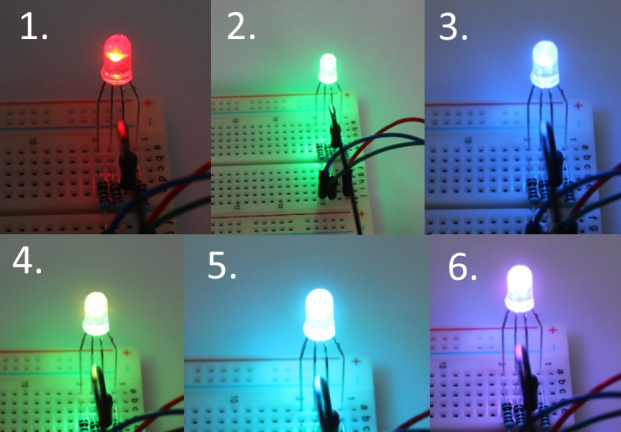
It is possible to create much more colours if you temper the colours. For example; you will get “yellow” by tempering “blue” and “green”.
There is a simple way to find out what RGB LED version you have. Just switch “+” and “-” on the LED. Only if the LED is connected the right way it will work and shine.
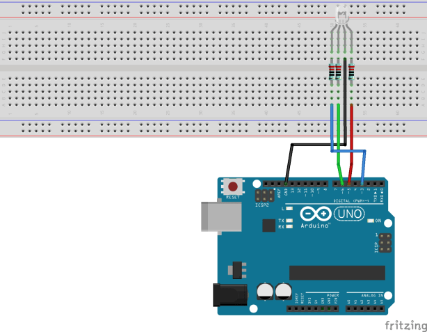
Setup with version a:
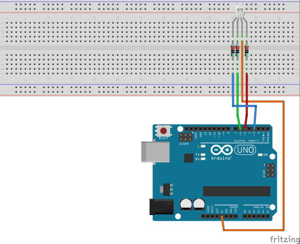
Setup for version b:

The Arduino is a digital Microcontroller. On its Outputs it only can “turn on” 5V or “turn off” 5V. But to create the different colours, the three colours of the LED have to be actuate more specific. That is the reason to use the Pulse Width Modulation. The PWM can be used on the pins with the little wave in front of the number.
The PWM lets the voltage pulse from +5V to 0V. So the voltage gets turned off and on for only milliseconds. With a really high PWM the 5 V signal nearly gets constant on the pin. With a low PWM it is the other way around and the 5 V signal is barely there (This is only a reduced summary, so you should look it up on the internet, if you need more information). With PWM it is possible to get nearly the same effect as if the voltage would vary.
The following codes are working for both RGB versions, but you have to note: In case of version b (Common anode), the value for “dark” has to bee 255. This means that there is not only a positive voltage at the positive pole of the LED, but also at each colour. In that case no current can flow between the contacts of the LED and the meant doesn’t light up. It means that the with version b, the colour gets brighter if the value gets smaller. The colour on pin 3 would light up bright if you choose the following value:
int brightnessblue=0;
Sketch 1:
With this code you can turn on and off the three different colours one by one.
int LEDblue=3; //Blue colour on pin 3
int LEDred=5; //Red colour on 5
int LEDgreen=6; //Green colour on pin 6
int b=1000; //b defines a break of 1000ms (1 second)
int brightnessblue=150; //Value between 0 and 255 – defines the brightness of the single colour
int brightnessred=150; //Value between 0 and 255 – defines the brightness of the single colour
int brightnessgreen=150; //Value between 0 and 255 – defines the brightness of the single colour
int dark=0; //Value 0 stands vor 0V voltage – therefore LED off
void setup()
{
pinMode(LEDblue, OUTPUT);
pinMode(LEDgreen, OUTPUT);
pinMode(LEDred, OUTPUT);
}
void loop()
{
analogWrite(LEDblue, brightnessblue); //Turn on blue
delay(b); //Break
analogWrite(LEDblue, dark); //Turn off blue
analogWrite(LEDred, brightnessred); //Turn on red
delay(b); //Break
analogWrite(LEDred, dark); // Turn off red
analogWrite(LEDgreen, brightnessgreen); //Turn on green
delay(b); //Break
analogWrite(LEDgreen, dark); //Turn off green
}
Sketch 2:
With this code always two different colours will be turned on and off together. This way we are able to create the colours yellow, turquoise and purple.
int LEDblue=3; //Blue colour on pin 3
int LEDred=5; //Red colour on 5
int LEDgreen=6; //Green colour on pin 6
int b=1000; //b defines a break of 1000ms (1 second)
int brightnessblue=150; //Value between 0 and 255 – defines the brightness of the single colour
int brightnessred=150; //Value between 0 and 255 – defines the brightness of the single colour
int brightnessgreen=150; //Value between 0 and 255 – defines the brightness of the single colour
int dark=0; //Value 0 stands vor 0V voltage – therefore LED off
void setup()
{
pinMode(LEDblue, OUTPUT);
pinMode(LEDgreen, OUTPUT);
pinMode(LEDred, OUTPUT);
}
void loop()
{
analogWrite(LEDgreen, brightnessgreen); //Green and red on = yellow
analogWrite(LEDred, brightnessred);
delay(b);
analogWrite(LEDgreen, dark); //Green and red off = yellow off
analogWrite(LEDred, dark);
analogWrite(LEDgreen, brightnessgreen); //Green and blue on = turquoise
analogWrite(LEDblue, brightnessblue);
delay(b);
analogWrite(LEDgreen, dark); //Green and blue off = turqouise off
analogWrite(LEDblue, dark);
analogWrite(LEDred, brightnessred); //Red an blue on = purple
analogWrite(LEDblue, brightnessblue);
delay(b);
analogWrite(LEDred, dark); //Red and blue off = purple off
analogWrite(LEDblue, dark);
}