The term „Arduino“ ist mostly used for both components. The hardware (Arduino Boards)
and the corresponding software (Arduino).
2.1 Hardware
The Arduino hardware is a so-called microcontrolling board (Following called „board“).
Basically it is a circuit board with many electronic parts around the actual microcontroller.
On the edge of the board are many pins with whom it is possible to connect different components. Some of them are for example: Switches, LED’s, Ultrasonic sensors, temperature sensors, displays, stepper, etc..
There are different kind of boards, that can be used with the Arduino sofware. Different sized “official” boards, with the official “Aduino” name on it, but also many, mostly cheaper, but equivalent Arduino “fitting” boards. Typical official boards are called Arduino UNO, Arduino MEGA, Arduino Mini, etc. Arduino compatible boards are for example Funduino UNO, Funduino MEGA, Freeduino, Seeduino, Sainsmart UNO etc..

2.1.2 Description of typical equipment
Beside sensors and actuators you need, as a base for quick and flexible experimental setups, jumper cable combined with a breadboard. This way you won’t need to solder.
Furthermore the LEDs are useful to check the signal output of the board.
2.1.2.1 Breadboard
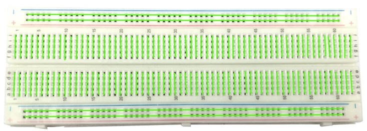
A Breadboard is a helpful tool to build circuits without any soldering. Certain contacts are connected with each other. Therefore it is possible to connect many cables with each other without soldering or screwing them together.
This image below shows in color, which contacts are connected.
2.1.2.2 LED (light emitting diode)
With LEDs it is possible to check the results of projects real quick. Because of that they’re useful for almost every Arduino project. On the internet are many information about LEDs.
The most important information:
The electricity can only get through the LED in one direction. So the LED has to be
connected the right way to work. There is a longer and a shorter contact at the LED.
The longer one is the positive (+) and the shorter one is the negative (–) contact.
The LED is only designed for a specific voltage. If there isn’t enough voltage the LED
won’t shine as bright as it should. If there’s to much voltage for the LED, it will get really hot (ATTENTION) and burn out.
Typical voltage data for the different colors of LEDs: blue: 3,1V, white: 3,3V, green: 3,7V,
yellow: 2,2V, red: 2,1V. The voltage on the microcontrollerboards is 5V. So the LED shouldn’t be connected to the board directly, but with a resistor between it in the circuit.
Non-committal recommendation for resistors at different LEDs (while connecting to the
5V pins on the microcontroller boards):
LED: white red yellow green blue IR
resistor: 100 Ohm 200 Ohm 200 Ohm 100 Ohm 100 Ohm 100 Ohm
2.2 Software
The software that is used to program the microcontroller, is open-source-software and can be downloaded for free on www.arduino.cc. With this “Arduino software” you can write little programs witch the microcontroller should perform. This programs are called “Sketch”.
In the end the sketches are transferred to the microcontroller by USB cable.
More on that later on the subject “programing”.
2.2.1 Installation
Now one after another the Arduino software and the USB driver for the board have to be installed.
2.2.1.1 Installation and set up of the Arduino software
1. Download the Arduino software on www.arduino.cc and install it on the computer (The microcontroller NOT connected to the PC). After that you open the software file and start the program named arduino.exe.
Two set ups on the program are important and should be considered.
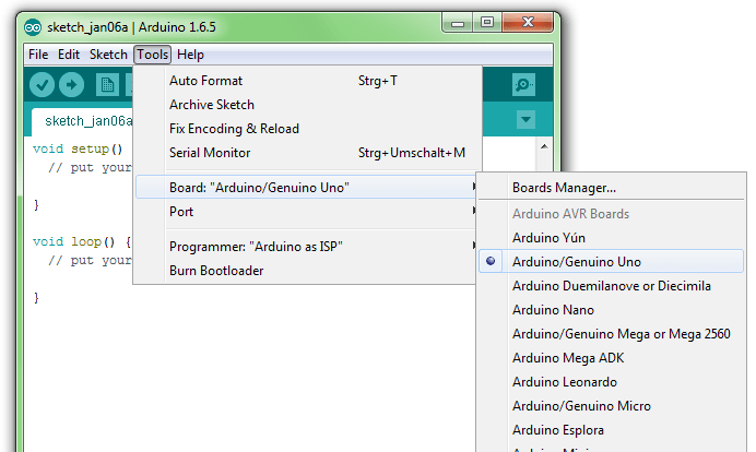
a) The board that you want to connect, has to be selected on the arduino software.
The “Funduino Uno” is here known as “Arduino / Genuino Uno”.
b) You have to choose the right “Serial-Port”, to let the Computer know to which port the board has been connected. That is only possible if the USB driver has been installed correctly. It can be checked this way:
At the moment the Arduino isn’t connected to the PC. If you now choose “Port”, under the field “Tool”, you will already see one or more ports here (COM1/ COM2/ COM3…).
The quantity of the shown ports doesn’t depend on the quantity of the USB ports on the computer. When the board gets connected to the computer, YOU WILL FIND ONE MORE PORT.

2.2.1.2 Installation of the USB driver
How it should be:
1. You connect the board to the computer.
2. The Computer recognizes the board and suggests to install a driver automatically.
ATTENTION: Wait a second! Most of the time the computer can’t find the driver automatically to install it. You might choose the driver by your own to install it. It can be found in the Arduino file under “Drivers”.
Control: At the control panel of the Computer you can find the “Device manager”. If the board has been installed successfully, it should appear here. When the installation has failed, there is either nothing special to find or you will find an unknown USB device with a yellow exclamation mark. In this case: Click on the unknown device and choose “update USB driver”. Now you can start over with the manual installation.