Now we can start properly. Without to much theoretical information we start directly with programming. Learning by doing. On the left side you can find the “sketches”, on the right the accompanying explanation for the commands in grey. If you work trough the tutorials with this system, you will soon understand the code and be able to use it by yourself. Later on you can familiarize yourself with other features. These tutorials are only meant as first steps to the Arduino world. All possible program features and codes are referred on www.arduino.cc under „reference“.
First of all a short explanation for possible error reports that can appear while working with the Arduino software. The two most common ones are:

1.) The board is not installed right or the wrong board is selected. After uploading
the sketch, there will appear an error report underneath the sketch. It looks like the one in the picture on the right. The note “not in sync” shows up in the error report.
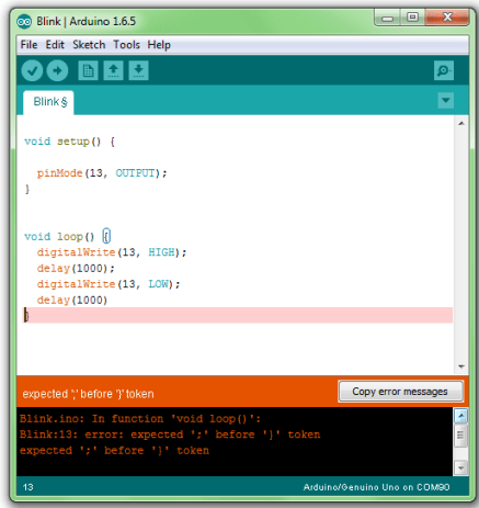
2.) There is a mistake in the sketch. For example, a word is misspelled or a bracket is missing. In the example on the left the last semicolon in the sketch is missing. In this Case the error report often starts with “excepted..”. This means that the program is still expecting something that is missing.
Basic structure of a sketch:
A sketch can be divided in three parts.
1. Name variable
In the first part elements of the program are named ( This will be explained in program no. 3). This part is not absolutely necessary.
2. Setup (absolutely necessary for the program)
The setup will be performed only once. Here you are telling the program for example what Pin (slot for cables) should be an input and what should be an output on the boards.
Defined as Output: The pin should put out a voltage. For example: With this pin a LED is meant to light up.
Defined as an Input: The board should read out a voltage. For example: A switch is actuated. The board recognized this, because it gets a voltage on the Input pin.
3. Loop (absolutely necessary for the program)
This loop part will be continuously repeated by the board. It assimilates the sketch from beginning to end and starts again from the beginning and so on.
Let’s start!