Task: A LED should light up if it gets dark or rather the photo resistor is covered.
Required equipment: Arduino/ One LED / Resistor with 200 Ohm / Resistor with 10K Ohm / Breadboard / Cables / Photo resistor
Learning content: Read out voltage and show out the values via “serial monitor”.
Read out voltage:
We want the microcontroller to recognize how bright it is by reading out a photo resistor.
For this purpose we will use a simple physical principle. If two consumers are connected in one circuit (series connection), they also “share” the applied voltage. Example: Two same lamps are connected in series with 6V applied voltage. With a voltmeter we are now able to measure only 3V on each lamp. If we would connect two different lamps (with different values of resistance), than we would be able to measure two different voltage values on each lamp, for example: 1,5V and 4,5V.
A photo resistor changes its resistance depending on the luminous intensity. We will use this effect to get a value for the brightness or darkness by reading out the applied voltage.
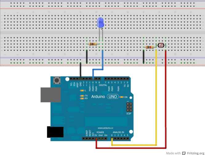
To create a split voltage we need to connect the photo resistor with a resistor (1-10K Ohm,
depending on what kind of photo resistor is used. The resistor should have nearly the same value of resistance as the used photo resistor.) in series. Now the circuit should get connected to ground (GND) and 5V (see setup).
The microcontroller is able to read out analogue signals (voltage) and work with the values. For this function the analog Inputs on the board are used. They are converting the voltage into a number, with that we are able to work with. 0 Volt corresponds to the number 0 and the highest measurable value 5V corresponds to the number 1023 (0 to 1023 are 1024 numbers = 10 Bit). Example: A voltage of 2,5V is measured, so the microcontroller would give out the value 512 (1024:2).
The “serial monitor”
An important tool of the arduino software is the “serial monitor”. With this “serial monitor” it is possible to show the read out data from the microcontroller (numbers or text). It is quite useful, because you will not always have an LCD-Monitor connected to show some values.
In this sketch we will use the “serial monitor” to get the values shown, which the microcontroller get from the photo resistor.
Why does that make sense? If we would want the LED to light up if it gets dark, there must be a function in the sketch, that defines: “If the value of the photo resistor gets lower that x, the LED is supposed to light up.” Therefore we have to know how high x is, while it starts to get darker.
Solution: We are going to display the value “x” from the photo resistor (while it is getting darker) on the “serial monitor”. Knowing this, we are later on able to get a function like this in the sketch: “If the read out voltage of the photo resistor gets lower that “x”, turn on the LED”.
Setup:
Code:
int input=A0; //”input” stands for the value “A0” (Label of the analog port 0)
int LED=10; //”LED” stands for the value 10
int sensorvalue=0; //variable for the sensor value with 0 as starting value
void setup() //The setup starts here
{
Serial.begin(9600); //Start the communication with the serial port. We will need this to get the read out //value of the photo resistor on the serial //monitor.
pinMode (LED,OUTPUT); //The pin connected with the LED gets defined as an output. We won’t need to define //the analog pin.
}
void loop()
{ //loop part starts here
sensorvalue=analogRead(input); //Read out the voltage of the photo resistor and save it under “sensorvalue”
Serial.print(„Sensor value =„); //Show “Sensor value=” on serial monitor
Serial.print(sensorvalue); //Send the value of the photo resistor as a number between 0 and 1023 to the //serial monitor
if(sensorvalue > 512) //If the sensor value gets higher than 512…
{
digitalWrite(LED,HIGH); //…the LED should light up…
}
else
{
digitalWrite(LED,LOW); //else the LED should be turned off
}
delay(50); //short break where the LED is turned on or off.
} //This last bracket closes the loop part
//If the sensor value for example at normal brightness only reaches 100 (this value depends on the used //resistor, the brightness and the current direction), it would make sense to use a lower value than 512 //(for example 90), to turn on the LED. You can look up the current sensor value on the “serial monitor”. //You can find it in the Arduino software at “tools”.