
The DS1307 I²C Real Time Clock module allows us to display the actual time and date on an LCD.
Required equipment:
Arduino / potentiometer / Breadboard / LCD Display / DS1307 I²C Real Time Clock / cables
Wiring:
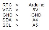
The Display has to be connected with the arduino just like in the tutorial no. 13 (Or see on the following setup). Now the RTC has to be connected to the arduino too:
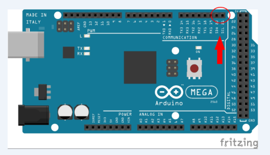
Attention!: The MEGA2560 R3 Controller has pins especially for SDA and SCL connections. These pins can be found on pin 20 and 21 on the board.
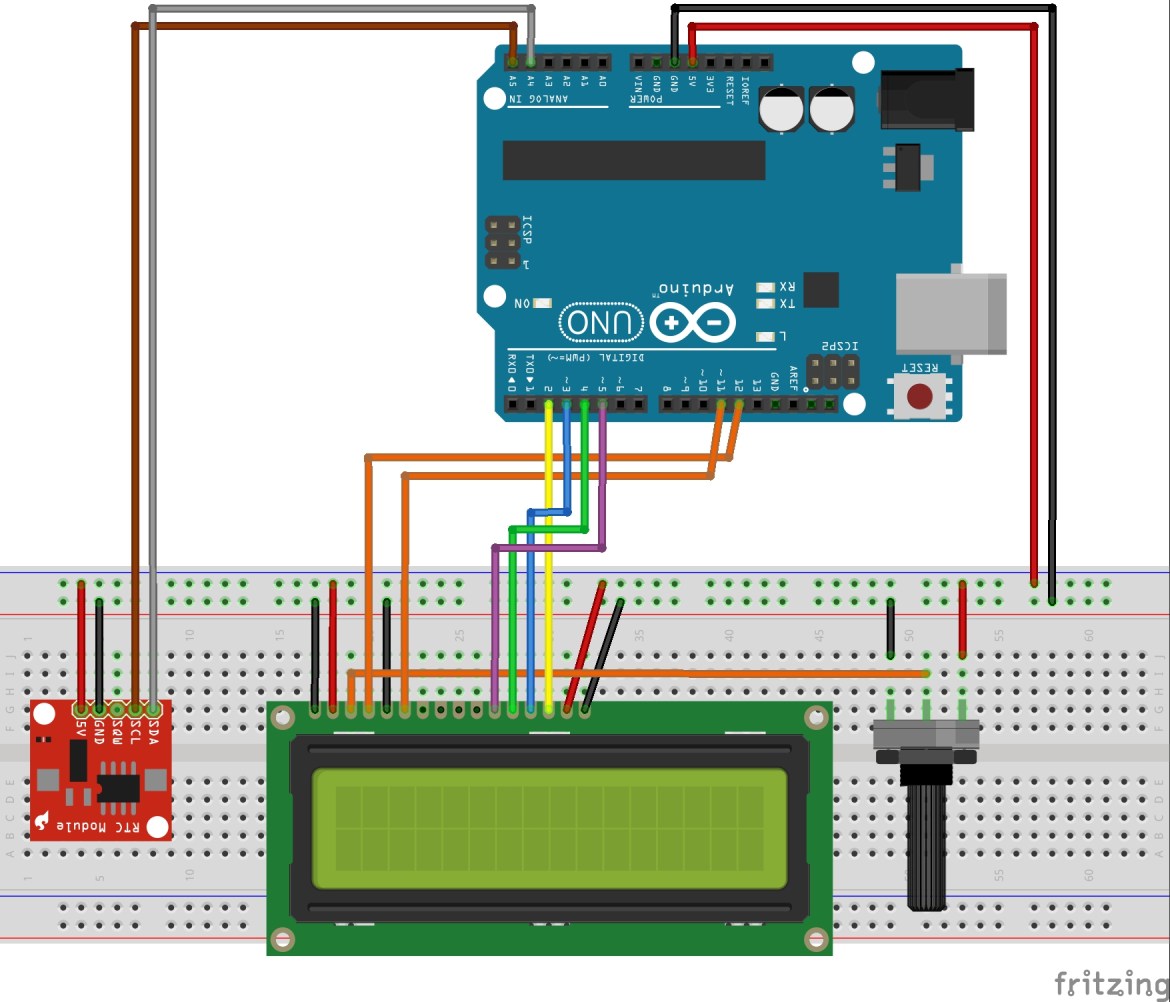
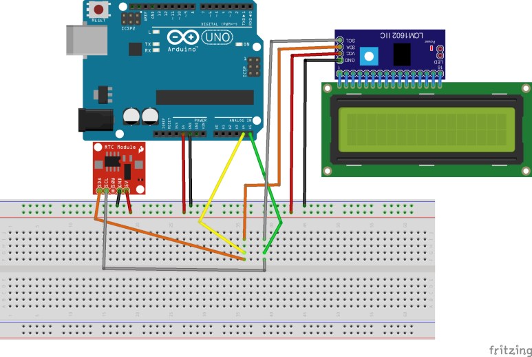
Setup with UNO R3:
If everything is connected, we are about to start the programming. But first we have to add two needed libraries for this sketch. The first library is the Time library, which can be downloaded here: http://www.pjrc.com/teensy/td_libs_Time.html and the DS1307RTC library, that can be downloaded here: http://www.pjrc.com/teensy/td_libs_DS1307RTC.html
Now if both libraries are downloaded we can add them to the arduino software. Sketch > Include Library > Add ZIP library > Choose the just downloaded library. If you have added both libraries, they can be used in the code from now on.
Now we have to upload the “Set-Time” Code, to set the time from your Computer or Laptop on the RTC. You can find the “Set-Time” Sketch at the Arduino software under File > Examples > DS1307RTC > Set Time. The “Set-Time” code opens up and has to be uploaded to the microcontroller.
Now we can continue with the actual code:
#include <Time.h> //Include Libraries
#include <Wire.h>
#include <DS1307RTC.h>
#include <LiquidCrystal.h>
LiquidCrystal lcd(12, 11, 5, 4, 3, 2); //The pins that are connected to the LCD are defined in this line
void setup() {
lcd.begin(16, 2); //The Display has 2 lines and 16 characters
Serial.begin(9600); //start serial connection with 9600 baud rate
setSyncProvider(RTC.get); //This function gets the date and time from the rtc
}
void loop() {
Serial.print(hour()); //Serial.print
printDigits(minute()); //the printDigits function is defined at the end of the code
printDigits(second());
Serial.print(“ „);
Serial.print(day());
Serial.print(“ „);
Serial.print(month());
Serial.print(“ „);
Serial.print(year());
Serial.println();
delay(1000); //wait a second
lcd.setCursor(4, 0); //The text begins at the third character on the first row
lcd.print(hour()); //The time is displayed in a hh:mm:ss format
lcd.print(„:“);
lcd.print (minute());
lcd.print(„:“);
lcd.print(second());
lcd.print(“ „);
lcd.setCursor(1, 1); //The next text begins at the second character on the second row
lcd.print(day()); //The date is displayed in a DD/MM/YYYY format
lcd.print(„/“);
lcd.print(month());
lcd.print(„/“);
lcd.print(year());
}
void printDigits(int digits){ //numbers <10 are shown with a “0” in front of the digits. This only applies //to the serial monitor not for the display
Serial.print(„:“);
if(digits < 10)
Serial.print(‚0‘);
Serial.print(digits);
}
Note: The DS1307 Real Time Clock is not accurate to the second, because the RTC can not compensate the about 15 seconds between uploading the Set Time Sketch and the final Sketch.
Additional to the time and date, it is possible to display the weekday in front of the date. We have to add the command printDay(); in front of the date at the lcd.print section and the following code after void Loop:
void printDay(){ //Define command void printDay
int day;
day = weekday(); //The weekdays are depending on the date
if(day == 1){lcd.print(„Su, „);}
if(day == 2){lcd.print(„Mo, „);}
if(day == 3){lcd.print(„Tu, „);}
if(day == 4){lcd.print(„We, „);}
if(day == 5){lcd.print(„Th, „);}
if(day == 6){lcd.print(„Fr, „);}
if(day == 7){lcd.print(„Sa, „);}
}
Extension
Using two I²C devices at the same time.
Showing the date and time from a Real Time Clock with I²C bus on an I²C LCD module.
If we want to run two I²C devices at the same time, one of the devices has to have a different I²C address. In this case we are only able to change the address of the I²C module. It has to be a I²C LCD with solder pads on the back, just like the one on the picture below.

The I²C address of the Real Time Clock is already set and can’t be changed.
In order to change the address of the LCD, the solder pads have to connected in a different way than at the beginning (all solder pads disconnected). In the following table you can see the different HEX addresses according to the solder pad connection combinations. ( I = connected, : = disconnected):
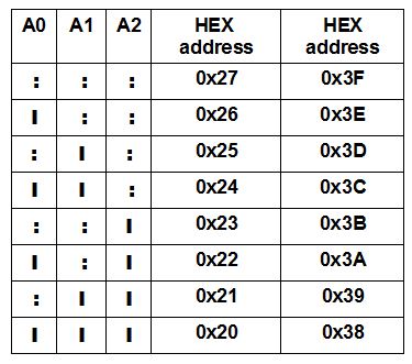
You can check it with the “Scanner” from the tutorial “Two I²C Displays at the same time” if you want to be sure.
Now if the address on the display has been changed we can go on to the wiring:
Programming:
We are going to need the DS1307RTC Library (Download link Above) and the NewliquidCrystal_1.3.4 Library, which can be downloaded here: https://bitbucket.org/fmalpartida/new-liquidcrystal/downloads
The Libraries have to be included to the Arduino software:
Sketch > Include Library > Add ZIP library > choose previous downloaded library
The next step is going to be uploading the “Set-Time” Sketch, in order to set the time from your PC on the Real Time Clock. The Set-Time Sketch can be found under File > Examples > DS1307RTC > Set Time. Now the Sketch can be uploaded and we can continue with the actual Code.
Code:
#include <Time.h>
#include <Wire.h>
#include <DS1307RTC.h>
#include <LiquidCrystal_I2C.h> //Include Libraries
LiquidCrystal_I2C lcd(0x3D, 2, 1, 0, 4, 5, 6, 7, 3, POSITIVE); //Name I²C display and the HEX address (in //our case: 0x3D)
void setup() {
lcd.begin(16, 2); //The Display has 2 lines and 16 characters
lcd.backlight(); //Turn on the backlight
Serial.begin(9600); //start serial connection with 9600 baud rate
setSyncProvider(RTC.get); //This function gets the date and time from the rtc
}
void loop() {
Serial.print(hour()); //Show time and date on serial monitor
printDigits(minute());
printDigits(second()); //the printDigits function is defined at the end of the code
Serial.print(“ „);
Serial.print(day());
Serial.print(“ „);
Serial.print(month());
Serial.print(“ „);
Serial.print(year());
Serial.println();
delay(1000); //wait a second
lcd.setCursor(2, 0); //The text begins at the third character on the first row
lcd.print(hour()); //The time is displayed in a hh:mm:ss format
lcd.print(„:“);
lcd.print (minute());
lcd.print(„:“);
lcd.print(second());
lcd.print(“ „);
lcd.setCursor(1, 1); //The next text begins at the second character on the second row The date is displayed //in a DD/MM/YYYY format
lcd.print(day());
lcd.print(„/“);
lcd.print(month());
lcd.print(„/“);
lcd.print(year());
}
void printDigits(int digits){ //numbers <10 are shown with a “0” in front of the digits. This only applies //to the serial monitor not for the display
Serial.print(„:“);
if(digits < 10)
Serial.print(‚0‘);
Serial.print(digits);
}