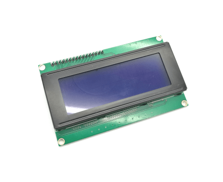
 The LCD module with the already soldered on i²C module, makes it possible to use an LCD without the complicated wiring. This can be useful for more complex projects. Another difference to the simple LCD is, that the module on the back of the LCD, already has got a knob for the adjusting of the back light. This four-line I²C LCD module has 20 characters in each of the four rows.
We are going to need the NewliquidCrystal_1.3.4 library, which can be downloaded on this website: https://bitbucket.org/fmalpartida/new-liquidcrystal/downloads
The library has to be added to the arduino software as always (see previous tutorials like I²C Display).
Required equipment: microcontroller (in this example UNO R3), 4×20 LCD with I²C module, cables
Task: Show a text on all four rows of the I²C LCD Module.
Wiring: The connection of the I²C LCD is very simple. The module has only four contacts.
GND gets connected to GND on the Arduino, VCC to 5V on the Arduino, SDA with the analog Input A4 and SCL to the analog Input A5.
LCD >> UNO
GND >> GND
VCC >> 5V
SDA >> A4
SCL >> A5
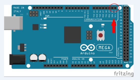
Attention!: The MEGA2560 microcontroller has its own SDA and SCL pins. You can find them on pin 20 and pin 21.

Code:
#include <Wire.h> //Include Wire library
#include <LiquidCrystal_I2C.h>//Include the previous downloaded NewliquidCrystal //library
LiquidCrystal_I2C lcd(0x27, 2, 1, 0, 4, 5, 6, 7, 3, POSITIVE); //In this line we //are calling the display „lcd“ and we are defining the address as “3x0F”
void setup()
{
lcd.begin(20,4); //Start the lcd and define how many rows and characters it has. 20 characters and 4 rows.
lcd.backlight();//Start the backlight
}
void loop()
{
lcd.setCursor(0,0); //Start the text in the first row at the first character
lcd.print(„First row test„); //Show the text “First row test”
lcd.setCursor(0,1); //Same principle with the next rows..
lcd.print(„Second row test„);
lcd.setCursor(0,2);
lcd.print(„Third row test„);
lcd.setCursor(0,3);
lcd.print(„fourth row test„);
}
